


Continuous pyrolysis plants can lose uptime because of unstable feeding, coke or wax buildup, pressure and sealing problems, and condensation or gas-handling issues. These problems can lead to blockages, unstable operation, frequent cleaning or safety alarms.
The most effective way to reduce downtime is to identify the source of the problem and address it through feedstock preparation, process configuration, temperature and pressure control, and automatic protection systems.
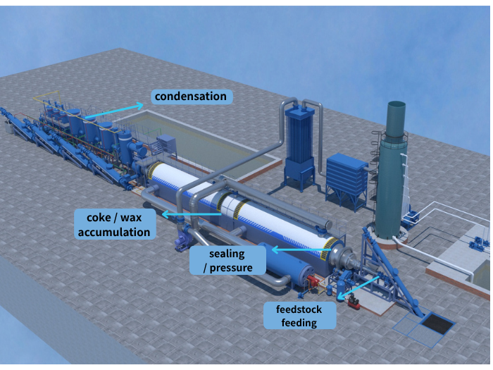 Continuous pyrolysis plant downtime and safety risks
DOING ECO has installation and commissioning experience with fully continuous pyrolysis projects, including 20 TPD continuous plastic pyrolysis equipment in Spain, 2 × 50 TPD continuous tire pyrolysis equipment in China, and 2 × 50 TPD continuous tire pyrolysis equipment in Poland. The following points focus on the main operating problems and practical ways to reduce them.
Inconsistent particle size, excessive impurities or unsuitable moisture can cause bridging, uneven feeding or overload of the feeding mechanism.
For continuous tire pyrolysis, another common issue is supplying whole tires to a system designed for prepared rubber particles or powder.
Start with feedstock preparation. The material entering the feeder should have a physical condition that matches the equipment design.
For continuous pyrolysis, feedstock preparation should match the material and feeding system. For waste tires, DOING ECO’s solutions are specified around approximately 2–20 mm prepared rubber particles or powder, with bead-wire removal and magnetic separation before feeding. This is a DOING ECO equipment specification, not a universal industry standard. Waste plastics may require sorting and shredding, while oil sludge may require moisture control and removal of large impurities.
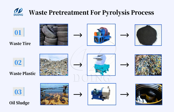 Pretreatment processes for various pyrolysis oil production feedstocks
Other feedstocks require different preparation. Waste plastics may need sorting and shredding, while oil sludge may require moisture control and removal of large impurities.
| Feedstock condition | What to control |
| Particle size | Match the prepared size to the feeder |
| Moisture | Control moisture where drying is required |
| Steel and impurities | Remove materials that may affect feeding |
| Feedstock composition | Confirm process compatibility |
| Daily supply | Maintain sufficient prepared feedstock for the planned TPD |
If feeding is already unstable, check the feedstock and feeder requirements first rather than immediately treating the reactor as the source of the problem.
Heavy components in pyrolysis vapor can condense or accumulate when process conditions are unsuitable. Coke can also build up in relevant sections of the system.
As deposits increase, they may restrict gas flow, increase pressure and create more frequent cleaning requirements.
Both wax accumulation and coke buildup need to be considered.
For relevant continuous pyrolysis designs, DOING ECO can use a wax-removal tank and catalyst to help reduce wax accumulation and improve pyrolysis oil quality, together with a dedicated coke-removal structure to deal with coke buildup.
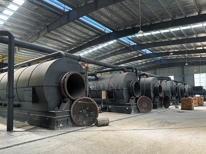 Doing ECO waste thermal decoking unit
Maintenance access is also important. Sections where deposits may form should be accessible for inspection and cleaning without unnecessary dismantling of the entire line.
For an existing plant, repeated pressure increases or frequent cleaning can be a reason to inspect the vapor path for deposits.
Continuous pyrolysis produces combustible gases and operates under oxygen-deficient conditions. Pressure fluctuations, poor sealing or air ingress can affect both process stability and safe operation.
Pressure changes may also be related to feeding, condensation or gas handling rather than the reactor itself.
The system needs effective pressure monitoring, sealing, air-ingress control and abnormal-condition protection.
DOING ECO continuous pyrolysis systems can be configured with PLC control, nitrogen purging and negative-pressure sealing.
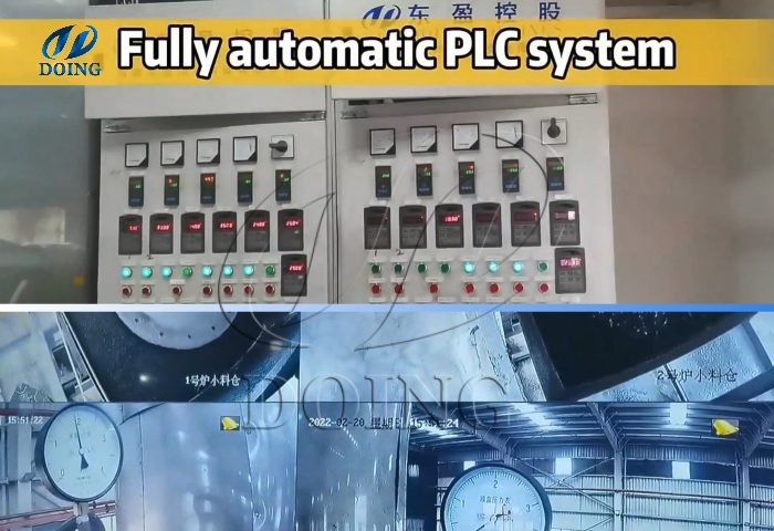 PLC safety control system for fully continuous waste pyrolysis equipment
In the 2026 Poland project with 2 × 50 TPD continuous tire pyrolysis plants, this sealing approach was used together with PLC-based monitoring and automatic alarm and interlock protection.
This is a project-specific configuration, not a universal requirement for every continuous pyrolysis plant.
If pressure is unstable, check the relationship between pressure changes and:
Feed rate
Reactor temperature
Condensation conditions
Gas flow
Seal condition
This helps identify the actual source instead of assuming every pressure problem comes from the reactor.
The reactor is only one part of a continuous pyrolysis line. Problems in condensation or gas handling can affect oil recovery, gas pressure and downstream stability.
Pyrolysis produces liquid, gas and solid fractions. The gaseous fraction can contain combustible components and may be reused as process fuel when the system is designed for this purpose.
The downstream process should be evaluated as one connected system:
Pyrolysis vapor → condensation → oil collection → gas separation → gas recycling or treatment
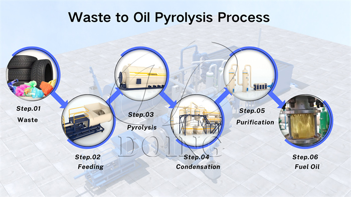 Process for producing pyrolysis oil from waste pyrolysis
When an operating problem occurs, compare temperature, pressure and flow before and after the affected section.
For example, if pressure changes after condensation conditions change, the problem may be in the condensation or gas-handling section rather than the reactor.
A clear process flow also makes troubleshooting and maintenance easier.
A continuous plant will experience changes in feed rate, temperature, pressure and gas conditions. The control system therefore needs to respond when operating parameters move outside their normal range.
DOING ECO continuous pyrolysis plants can use PLC-based control to monitor operating conditions. Depending on the project configuration, alarms, interlocks and shutdown actions can be used to respond to abnormal conditions.
For a new project, the response logic should be clear:
Parameter change → alarm → interlock or operator response → feeding/heating action → safe shutdown if required
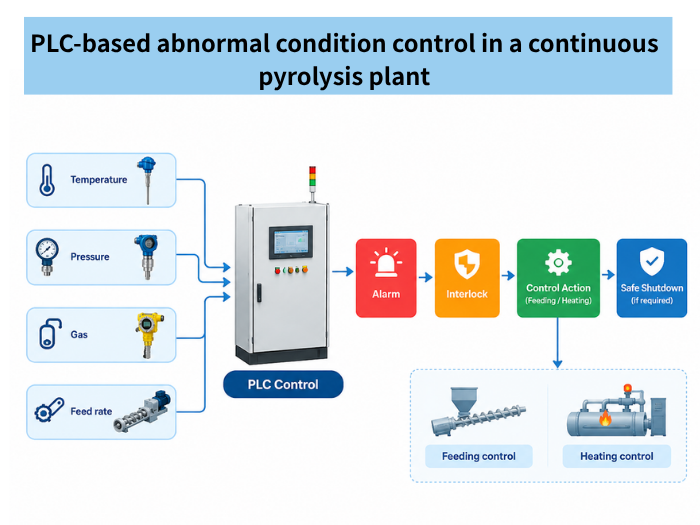 PLC monitoring and safety response for continuous pyrolysis equipment
The exact sensors, alarm points and shutdown sequence should be defined according to the actual process and equipment configuration.
| Operating problem | Areas to check first |
| Unstable feeding | Particle size, moisture, impurities and feeder condition |
| Increasing pressure | Coke/wax buildup, condensation and gas flow |
| Sudden pressure fluctuation | Feeding, sealing, temperature and gas handling |
| Changing oil recovery | Condensation temperature, vapor flow and downstream conditions |
| Frequent cleaning | Wax/coke accumulation and maintenance access |
| Repeated safety alarms | Sensors, process conditions, interlocks and operating procedures |
For an existing plant, this checklist can help narrow down the source of downtime. For a new project, the same points can be reviewed during equipment design to reduce potential operating problems before installation.
Ask for comparable continuous project experience and technical information covering feedstock requirements, control systems, gas handling and maintenance. Project configuration is more useful to review than a capacity figure alone.
The operating mode alone does not determine safety. Factors such as sealing, pressure control, gas handling, interlocks and operating procedures are also important.
There is no single maintenance interval for every design. Cleaning, seal inspection and wear-part replacement depend on the equipment, feedstock and operating conditions.
If you are troubleshooting an existing plant or planning a new continuous pyrolysis project, start with feedstock type, prepared particle size, target TPD and project location.
DOING ECO can review these conditions and recommend the appropriate pretreatment, feeding, pyrolysis, condensation and gas-handling configuration for the project.

